OpenCASCADE Linear Extrusion Surface
eryar@163.com
Abstract. OpenCASCADE linear extrusion surface is a generalized cylinder. Such a surface is obtained by sweeping a curve (called the “extruded curve” or “basis”) in a given direction (referred to as the direction of extrusion and defined by a unit vector). The u parameter is along the extruded curve. The v parameter is along the direction of extrusion. The form of a surface of linear extrusion is generally a ruled surface. It can be a cylindrical surface, or a planar surface.
Key Words. OpenCASCADE, Extrusion Surface, Sweeping
1. Introduction
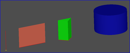
一般柱面(The General Cylinder)可以由一段或整个圆弧沿一个方向偏移一定的距离得到。如下图所示:

Figure 1.1 Extrusion Shapes
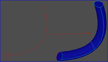
当将顶点拉伸时,会生成一条边;当将边拉伸时,会生成面;当将Wire拉伸时,会生成Shell,当将面拉伸时,会生成体。当将曲线沿一个方向拉伸时,会形成一个曲面,如果此方向为直线,则会生成一般柱面。如果此方向是曲线时,会生成如下图所示曲面:

Figure 1.2 Swept surface/ loft surface
本文主要介绍将曲线沿直线方向拉伸的算法,即一般柱面生成算法。并将生成的曲面在OpenSceneGraph中进行显示。
2.Cylinder Surface Definition
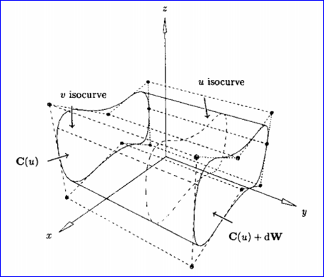
设W是一个单位向量,C(u)是定义在节点矢量U上,权值为wi的p次NURBS曲线。我们要得到一般柱面S(u,v)的表达式,S(u,v)是通过将C(u)沿方向W平行扫描(sweep)距离d得到的。记扫描方向的参数为v, 0<v<1,显然,S(u,v)必须满足以下两个条件:
v 对于固定的u0, S(u0, v)为由C(u0)到C(u0)+dW的直线段;
v 对于固定的v0:

所要求的柱面的表达式为:

S(u,v)定义在节点矢量U和V上,这里V={0,0,1,1},U为C(u)的节点矢量。控制顶点由Pi,0=Pi和Pi,1=Pi+dW给出,权值wi,0=wi,1=wi。如下图所示为一般柱面:

Figure 2.1 A general cylinder obtained by translating C(u) a distance d along W.
其中OpenCASCADE中一般柱面的表达式如下所示:

其取值范围的代码如下所示:
//=======================================================================
//function : Bounds
//purpose :
//=======================================================================
void Geom_SurfaceOfLinearExtrusion::Bounds ( Standard_Real& U1,
Standard_Real& U2,
Standard_Real& V1,
Standard_Real& V2 ) const {
V1 = -Precision::Infinite(); V2 = Precision::Infinite();
U1 = basisCurve->FirstParameter(); U2 = basisCurve->LastParameter();
}
由上代码可知,参数在v方向上是趋于无穷的;在u方向上参数的范围为曲线的范围。计算柱面上点的方法代码如下所示:
//=======================================================================
//function : D0
//purpose :
//=======================================================================
void Geom_SurfaceOfLinearExtrusion::D0 (const Standard_Real U,
const Standard_Real V,
Pnt& P) const {
XYZ Pxyz = direction.XYZ();
Pxyz.Multiply (V);
Pxyz.Add (basisCurve->Value (U).XYZ());
P.SetXYZ(Pxyz);
}
即将柱面上点先按V方向来计算,再按U方向来计算,最后将两个方向的值相加即得到柱面上的点。
由上述代码可知,OpenCASCADE中一般柱面没有使用NURBS曲面来表示。根据这个方法,可以将任意曲线沿给定的方向来得到一个柱面,这个曲线可以是直线、圆弧、圆、椭圆等。关于柱面上更多算法,如求微分等,可以参考源程序。
3.Display the Surface
还是在OpenSceneGraph中来对一般柱面进行可视化,来验证结果。因为OpenSceneGraph的简单易用,显示曲面的程序代码如下所示:
/*
* Copyright (c) 2013 to current year. All Rights Reserved.
*
* File : Main.cpp
* Author : eryar@163.com
* Date : 2014-11-23 10:18
* Version : OpenCASCADE6.8.0
*
* Description : Test the Linear Extrusion Surface of OpenCASCADE.
*
* Key Words : OpenCascade, Linear Extrusion Surface, General Cylinder
*
*/
// OpenCASCADE.
#define WNT
#include <Precision.hxx>
#include <gp_Circ.hxx>
#include <Geom_SurfaceOfLinearExtrusion.hxx>
#include <GC_MakeCircle.hxx>
#include <GC_MakeSegment.hxx>
#include <GC_MakeArcOfCircle.hxx>
#pragma comment(lib, "TKernel.lib")
#pragma comment(lib, "TKMath.lib")
#pragma comment(lib, "TKG3d.lib")
#pragma comment(lib, "TKGeomBase.lib")
// OpenSceneGraph.
#include <osgViewer/Viewer>
#include <osgViewer/ViewerEventHandlers>
#include <osgGA/StateSetManipulator>
#pragma comment(lib, "osgd.lib")
#pragma comment(lib, "osgGAd.lib")
#pragma comment(lib, "osgViewerd.lib")
const double TOLERANCE_EDGE = 1e-6;
const double APPROXIMATION_DELTA = 0.05;
/**
* @brief Render 3D geometry surface.
*/
osg::Node* BuildSurface(const Handle_Geom_Surface& theSurface)
{
osg::ref_ptr<osg::Geode> aGeode = new osg::Geode();
Standard_Real aU1 = 0.0;
Standard_Real aV1 = 0.0;
Standard_Real aU2 = 0.0;
Standard_Real aV2 = 0.0;
Standard_Real aDeltaU = 0.0;
Standard_Real aDeltaV = 0.0;
theSurface->Bounds(aU1, aU2, aV1, aV2);
// trim the parametrical space to avoid infinite space.
Precision::IsNegativeInfinite(aU1) ? aU1 = -1.0 : aU1;
Precision::IsInfinite(aU2) ? aU2 = 1.0 : aU2;
Precision::IsNegativeInfinite(aV1) ? aV1 = -1.0 : aV1;
Precision::IsInfinite(aV2) ? aV2 = 1.0 : aV2;
// Approximation in v direction.
aDeltaU = (aU2 - aU1) * APPROXIMATION_DELTA;
aDeltaV = (aV2 - aV1) * APPROXIMATION_DELTA;
for (Standard_Real u = aU1; (u - aU2) <= TOLERANCE_EDGE; u += aDeltaU)
{
osg::ref_ptr<osg::Geometry> aLine = new osg::Geometry();
osg::ref_ptr<osg::Vec3Array> aPoints = new osg::Vec3Array();
for (Standard_Real v = aV1; (v - aV2) <= TOLERANCE_EDGE; v += aDeltaV)
{
gp_Pnt aPoint = theSurface->Value(u, v);
aPoints->push_back(osg::Vec3(aPoint.X(), aPoint.Y(), aPoint.Z()));
}
// Set vertex array.
aLine->setVertexArray(aPoints);
aLine->addPrimitiveSet(new osg::DrawArrays(osg::PrimitiveSet::LINE_STRIP, 0, aPoints->size()));
aGeode->addDrawable(aLine.get());
}
// Approximation in u direction.
for (Standard_Real v = aV1; (v - aV2) <= TOLERANCE_EDGE; v += aDeltaV)
{
osg::ref_ptr<osg::Geometry> aLine = new osg::Geometry();
osg::ref_ptr<osg::Vec3Array> aPoints = new osg::Vec3Array();
for (Standard_Real u = aU1; (u - aU2) <= TOLERANCE_EDGE; u += aDeltaU)
{
gp_Pnt aPoint = theSurface->Value(u, v);
aPoints->push_back(osg::Vec3(aPoint.X(), aPoint.Y(), aPoint.Z()));
}
// Set vertex array.
aLine->setVertexArray(aPoints);
aLine->addPrimitiveSet(new osg::DrawArrays(osg::PrimitiveSet::LINE_STRIP, 0, aPoints->size()));
aGeode->addDrawable(aLine.get());
}
return aGeode.release();
}
/**
* @brief Build the test scene.
*/
osg::Node* BuildScene(void)
{
osg::ref_ptr<osg::Group> aRoot = new osg::Group();
// test the linear extrusion surface.
// test linear extrusion surface of a line.
Handle_Geom_Curve aSegment = GC_MakeSegment(gp_Pnt(3.0, 0.0, 0.0), gp_Pnt(6.0, 0.0, 0.0));
Handle_Geom_Surface aPlane = new Geom_SurfaceOfLinearExtrusion(aSegment, gp::DZ());
aRoot->addChild(BuildSurface(aPlane));
// test linear extrusion surface of a arc.
Handle_Geom_Curve aArc = GC_MakeArcOfCircle(gp_Circ(gp::ZOX(), 2.0), 0.0, M_PI, true);
Handle_Geom_Surface aSurface = new Geom_SurfaceOfLinearExtrusion(aArc, gp::DY());
aRoot->addChild(BuildSurface(aSurface));
// test linear extrusion surface of a circle.
Handle_Geom_Curve aCircle = GC_MakeCircle(gp::XOY(), 1.0);
Handle_Geom_Surface aCylinder = new Geom_SurfaceOfLinearExtrusion(aCircle, gp::DZ());
aRoot->addChild(BuildSurface(aCylinder));
return aRoot.release();
}
int main(int argc, char* argv[])
{
osgViewer::Viewer aViewer;
aViewer.setSceneData(BuildScene());
aViewer.addEventHandler(new osgGA::StateSetManipulator(
aViewer.getCamera()->getOrCreateStateSet()));
aViewer.addEventHandler(new osgViewer::StatsHandler);
aViewer.addEventHandler(new osgViewer::WindowSizeHandler);
return aViewer.run();
return 0;
}
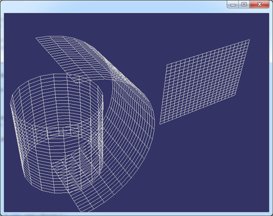
上述显示方法只是显示线框的最简单的算法,只为验证一般柱面结果,不是高效算法。显示结果如下图所示:

Figure 3.1 General Cylinder for: Circle, Arc, Line
如上图所示分别为对圆、圆弧和直线进行拉伸得到的一般柱面。根据这个原理可以将任意曲线沿给定方向进行拉伸得到一个柱面。
4.Conclusion
通过对OpenCASCADE中一般柱面的类中代码进行分析可知,OpenCASCADE的这个线性拉伸柱面Geom_SurfaceOfLinearExtrusion是根据一般柱面的定义实现的,并不是使用NURBS曲面来表示的。当需要用NURBS曲面来表示一般柱面时,需要注意控制顶点及权值的计算取值。
5. References
1. 赵罡,穆国旺,王拉柱译. 非均匀有理B样条. 清华大学出版社. 2010
2. Les Piegl, Wayne Tiller. The NURBS Book. Springer-Verlag. 1997
3. OpenCASCADE Team, OpenCASCADE BRep Format. 2014
4. Donald Hearn, M. Pauline Baker. Computer Graphics with OpenGL. Prentice Hall. 2009
5. 莫蓉,常智勇. 计算机辅助几何造型技术. 科学出版社. 2009