OpenCASCADE 麻花钻头造型实例分析
eryar@163.com
Abstract. OpenCASCADE provides a simple twist drill bit modeling example in Tcl script. The blog will give a details of some key points, when you understand the key points, you can modeling the shape like that.
Key Words. OpenCASCADE, Twist Drill Bit Modeling, Tcl
1.Introduction
OpenCASCADE的Draw Test Harness中提供了一个麻花钻头造型的实例,如下图所示:
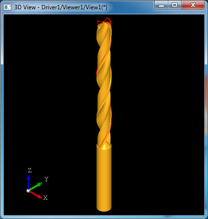
Figure 1. A Simple Twist Drill Bit by OpenCASCADE
钻头造型主要涉及到旋转形状的造型方法,放样造型及布尔操作。本文结合钻头的Tcl脚本来详细说明造型过程。对于有同样造型需求的,可以在理解造型方法的基础上实现自己需要的参数化形状。
2.Modeling Tcl Script
通过Draw Test Harness的菜单Samples->View samples可以找到Drill例子,如下图所示:
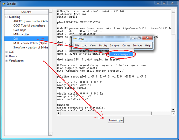
Figure 2. Drill bit modeling sample
对应的Tcl脚本位于samples/tcl文件夹中,列出如下:
# Sample: creation of simple twist drill bit
#Category: Modeling
#Title: Drill

pload MODELING VISUALIZATION
# drill parameters (some terms taken from http://www.drill-bits.cn/drill-bits-quality.asp)

dset R  4.    ;# outer radius

dset D  2*R   ;# diameter

dset Rr 3.5   ;# chisel radius (outer radius minus body clearance)

dset b  1.    ;# web thickness (approximate)

dset d  b/2
dset H  80.   ;# height of the spiral part

dset a  3.*pi ;# total angle of spiral rotation

dset sigma 118 ;# point angle, in degrees
# Create section profile by sequence of Boolean operations
# on simple planar objects

puts "Creating the drill section profile..."
polyline rectangle1 d -R 0  R -R 0 -d R 0 -R R 0  d -R 0
circle circle1 0 0 0 0 0 1 R
mkedge circle1 circle1
wire circle1 circle1
circle circle2 0 0 0 0 0 1 Rr
mkedge circle2 circle2
wire circle2 circle2
plane p0
mkface rectangle1 p0 rectangle1
mkface circle1 p0 circle1
mkface circle2 p0 circle2
bcommon sec rectangle1 circle1
# note use of 'fuse' instead of 'bfuse' -- we need to get single face

fuse sec sec circle2
# Construct flute profile so as to have cutting lip straight after sharpening.
# Here we need to take into account spiral shift of the flute edge
# along the point length -- the way to do that is to make spiral
# from the desired cutting lip edge and then intersect it by plane

polyline lip d -d/2 0  d -R -R/tan(sigma/2*pi/180)
polyline sp 0 0 0 0 0 H
cylinder cc 0 0 0 0 0 1 0 -4 0 4
line ll 0 0 a 80
trim ll ll 0 sqrt(a*a+H*H)
vertex v1 0 -R 0
vertex v2 0 -R H
trotate v2 0 0 0 0 0 1 180.*a/pi
mkedge ee ll cc v1 v2
wire gg ee
mksweep sp
setsweep -G gg 0 0
addsweep lip
buildsweep spiral -S
mkface f0 p0 -R R -R R
bsection sflute spiral f0
# here we rely on that section curve is parameterized from 0 to 1
# and directed as cutting lip edge;
# note that this can change if intersection algorithm is modified

explode sflute e
mkcurve cflute sflute_1
cvalue cflute 0. x0 y0 z0
cvalue cflute 1. x1 y1 z1
vertex vf0 x0 y0 z0
vertex vf1 x1 y1 z1
# -- variant: replace curve by arc with start at x0,y0,z0 and end at x1,y1,z1,
# -- such that tanget at start point is along Y
#dset Rflute ((x1-x0)*(x1-x0)+(y1-y0)*(y1-y0))/(2*(x1-x0))
#circle aflute x0+Rflute y0 0  0 0 1  Rflute
#mkedge sflute_1 aflute vf0 vf1
# make rounding in the flute; use circle with radius Rr/2

circle cround x0+Rr/2 y0 0 0 0 1 Rr/2
vertex vf3 x0+Rr y0 0
mkedge sflute_2 cround vf3 vf0
vertex vf2 R -R 0
edge sflute_3 vf3 vf2
edge sflute_4 vf2 vf1
wire w2 sflute_1 sflute_2 sflute_3 sflute_4
mkface flute p0 w2
# cut flute from profile

bcut sec sec flute
trotate flute 0 0 0 0 0 1 180.
bcut sec sec flute
donly sec
# sweep profile to get a drill body

puts "Sweeping the profile..."
mksweep sp
setsweep -G gg 0 0
explode sec w
addsweep sec_1
buildsweep base -S
# sharpen the drill (see http://tool-land.ru/zatochka-sverla.php)

puts "Sharpening..."
dset theta a*R/H*sin((90-sigma/2)*pi/180)
plane ax1 d 1.9*D "H+1.9*D/tan(pi/180.*sigma/2.)" 0 -1 -1
pcone sh1 ax1 0 100*sin((sigma-90)/2*pi/180.) 100
trotate sh1 0 0 0 0 0 1 -theta*180/pi
tcopy sh1 sh2
trotate sh2 0 0 0 0 0 1 180
box sh -D/2 -D/2 72 D D 20
bcommon qq sh1 sh2
bcut sharpener sh qq
bcut body base sharpener
# make a shank

puts "Making a shank..."
plane pl2 0 0 -40 0 0 1
pcylinder shank pl2 4 40
pcone transit R 0 R
plane pl3 0 0 -40 0 0 -0.5
pcone tail pl3 R 0 0.5
bfuse shank shank tail
bfuse shank shank transit
bfuse drill body shank
# check result

checkshape drill
# show result

puts "Displaying result..."
incmesh drill 0.01
vdisplay drill
vsetdispmode drill 1
vrenderparams -msaa 8
vfit
# show section and sweep path

ttranslate sec_1 0 0 H; trotate sec_1 0 0 0 0 0 1 a*180/pi; incmesh gg 0.01; vdisplay gg sec_1
下面结合Tcl脚本来对钻头的造型过程进行详细说明。
3.Twist Drill Bit Parameters
脚本首先加载相应的模块:造型模块和显示模块,分别为MODEING和VISUALIZATION。然后设置钻头相关参数变量:

Figure 3. Drill Bit
变量名及其说明:
| 变量名variable |
说明 detail |
| R |
外半径 outer radius |
| D |
直径D |
| Rr |
Chisel Radius |
| b |
Web thickness(approximate) |
| d |
|
| H |
螺旋部分的高度Height of the spiral height |
| a |
螺旋角度Total angle of spiral rotation |
| sigma |
钻尖角度Point angle in degrees. |
先定义这些变量的思想也是参数化的思想,将这些变量值改变就会得到不同的钻头模型。参数化的思想在CAD软件中比较常见,如AutoCAD中的动态块,PDMS中的设备模板Template等,都属于参数化的方法。通过修改参数让一个或多个几何体形状发生变化。
4.Create Drill Section Profile
创建钻头截面的Tcl脚本如下所示:
# Create section profile by sequence of Boolean operations
# on simple planar objects

puts "Creating the drill section profile..."
polyline rectangle1 d -R 0  R -R 0 -d R 0 -R R 0  d -R 0
circle circle1 0 0 0 0 0 1 R
mkedge circle1 circle1
wire circle1 circle1
circle circle2 0 0 0 0 0 1 Rr
mkedge circle2 circle2
wire circle2 circle2
plane p0
mkface rectangle1 p0 rectangle1
mkface circle1 p0 circle1
mkface circle2 p0 circle2
bcommon sec rectangle1 circle1
# note use of 'fuse' instead of 'bfuse' -- we need to get single face

fuse sec sec circle2
生成的图形如下图所示:
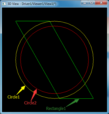
Figure 4 Profile construction curves
其中变量Rectangle1是图中绿色表示的四边形,Circle1是黄色表示的外圆,Circle2是红色表示的内圆。通过布尔操作求取Rectangle1和Circle1的公共部分得到如下图所示的截面:
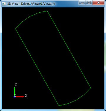
Figure 5 Common of Rectangle1 and Circle1
将公共部分与内圆Circle2合并得到如图所示截面:
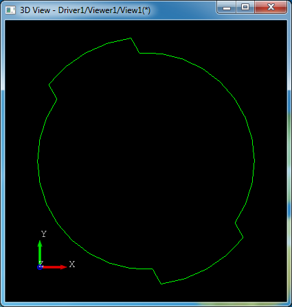
Figure 6. Fuse of Common part and Circle2
下面在这个截面的基础上生成钻头的螺旋凹槽,这里是相对关键的地方,生成凹槽的时候还要考虑螺旋。
# Construct flute profile so as to have cutting lip straight after sharpening.
# Here we need to take into account spiral shift of the flute edge
# along the point length -- the way to do that is to make spiral
# from the desired cutting lip edge and then intersect it by plane

polyline lip d -d/2 0  d -R -R/tan(sigma/2*pi/180)
polyline sp 0 0 0 0 0 H
cylinder cc 0 0 0 0 0 1 0 -4 0 4
line ll 0 0 a 80
trim ll ll 0 sqrt(a*a+H*H)
vertex v1 0 -R 0
vertex v2 0 -R H
trotate v2 0 0 0 0 0 1 180.*a/pi
mkedge ee ll cc v1 v2
wire gg ee
mksweep sp
setsweep -G gg 0 0
addsweep lip
buildsweep spiral -S
mkface f0 p0 -R R -R R
bsection sflute spiral f0
代码生成的图形如下图所示:
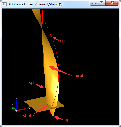
Figure 7. Flute of the drill bit
通过将线lip沿着路径直线sp和螺旋线gg放样得到螺旋截面spiral,再将螺旋截面spiral和底平面f0求交得到sflute。
# here we rely on that section curve is parameterized from 0 to 1
# and directed as cutting lip edge;
# note that this can change if intersection algorithm is modified

explode sflute e
mkcurve cflute sflute_1
cvalue cflute 0. x0 y0 z0
cvalue cflute 1. x1 y1 z1
vertex vf0 x0 y0 z0
vertex vf1 x1 y1 z1
# -- variant: replace curve by arc with start at x0,y0,z0 and end at x1,y1,z1,
# -- such that tanget at start point is along Y
#dset Rflute ((x1-x0)*(x1-x0)+(y1-y0)*(y1-y0))/(2*(x1-x0))
#circle aflute x0+Rflute y0 0  0 0 1  Rflute
#mkedge sflute_1 aflute vf0 vf1
# make rounding in the flute; use circle with radius Rr/2

circle cround x0+Rr/2 y0 0 0 0 1 Rr/2
vertex vf3 x0+Rr y0 0
mkedge sflute_2 cround vf3 vf0
vertex vf2 R -R 0
edge sflute_3 vf3 vf2
edge sflute_4 vf2 vf1
wire w2 sflute_1 sflute_2 sflute_3 sflute_4
mkface flute p0 w2
通过求得的交线再构造圆弧和线段来构造出钻头凹槽的截面,如下图所示:
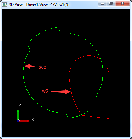
Figure 8. Make flute section
将凹槽截面flute从前面构造的截面中去除:
# cut flute from profile

bcut sec sec flute
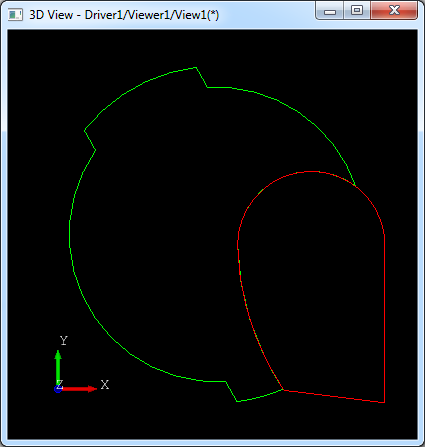
Figure 9. Make drill bit profile
将凹槽截面绕Z轴旋转180度,再去布尔减原来的截面:
trotate flute 0 0 0 0 0 1 180.
bcut sec sec flute
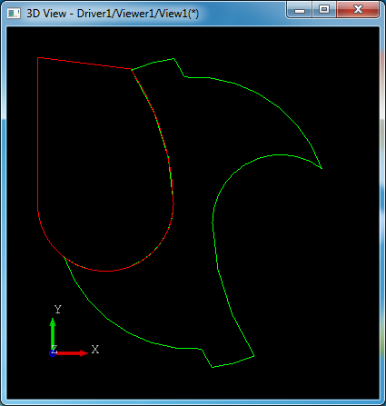
Figure 10. Make drill bit profile
这样钻头的截面就生成了。
5.Sweeping the Profile
将上面钻头截面沿着直线sp和螺旋线gg放样:
# sweep profile to get a drill body

puts "Sweeping the profile..."
mksweep sp
setsweep -G gg 0 0
explode sec w
addsweep sec_1
buildsweep base -S
生成图形如下图所示:
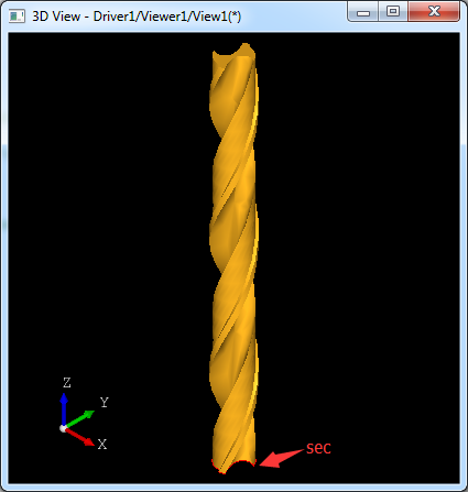
Figure 11. Sweep the profile
通过放样得到了钻头的螺杆base。
6.Sharpening
得到钻头的螺杆后需要生成钻头的钻尖,根据钻尖角point angle变量sigma来造型。
# sharpen the drill (see http://tool-land.ru/zatochka-sverla.php)

puts "Sharpening..."
dset theta a*R/H*sin((90-sigma/2)*pi/180)
plane ax1 d 1.9*D "H+1.9*D/tan(pi/180.*sigma/2.)" 0 -1 -1
pcone sh1 ax1 0 100*sin((sigma-90)/2*pi/180.) 100
trotate sh1 0 0 0 0 0 1 -theta*180/pi
tcopy sh1 sh2
trotate sh2 0 0 0 0 0 1 180
box sh -D/2 -D/2 72 D D 20
bcommon qq sh1 sh2
bcut sharpener sh qq
bcut body base sharpener
先构造两个圆锥体(sh1和sh2)和一个长方体sh,再通过布尔运算得到两个圆锥体sh1,sh2的公共部分qq。如下图所示:

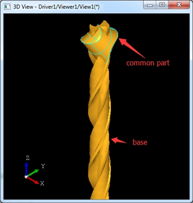
Figure 12. Modeling point angle
再从长方体sh中减去两个圆锥的公共部分得到如下图所示:
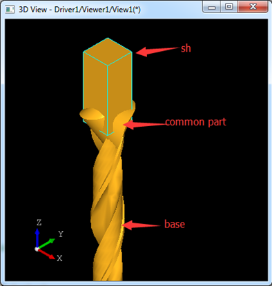
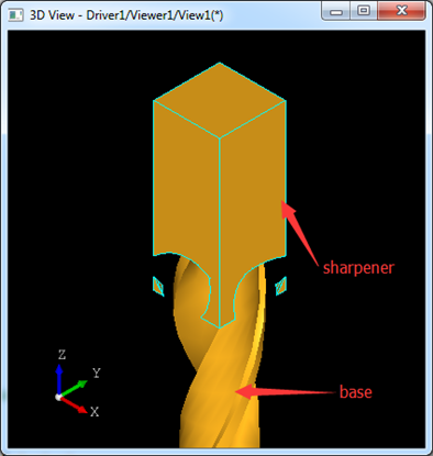
Figure 13. Modeling point angle
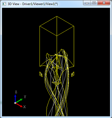
将螺杆减去上面得到的sharpener就完成钻尖的造型,如下图所示:

Figure 14. Modeling point angle
7.Make Shank
完成螺杆和钻尖造型后,就来实现麻花钻头的最后部分,钻头柄shank。
# make a shank

puts "Making a shank..."
plane pl2 0 0 -40 0 0 1
pcylinder shank pl2 4 40
pcone transit R 0 R
plane pl3 0 0 -40 0 0 -0.5
pcone tail pl3 R 0 0.5
bfuse shank shank tail
bfuse shank shank transit
bfuse drill body shank
钻头柄部由两个圆锥(transit和tail)和一个圆柱shank组成。最后将这三个形状合并得到完成的钻头的柄部shank。
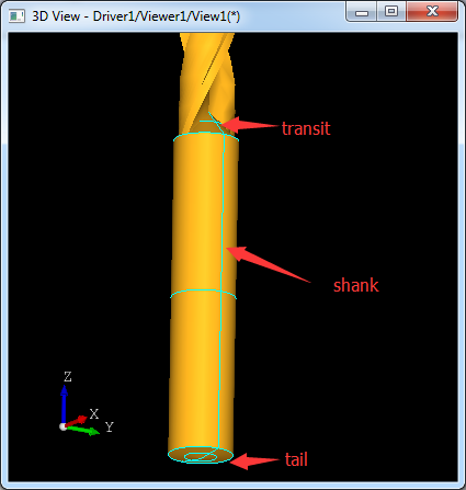
Figure 15. Modeling Shank
8.Conclusion
通过对OpenCASCADE中麻花钻头的造型实例分析,可见这个钻头造型用到的算法主要是放样及布尔操作。在生成螺旋线时主要是使用pcurve的方式。最后还要理解参数化的造型思想,通过定义变量来生成参数化的模型。