Summary
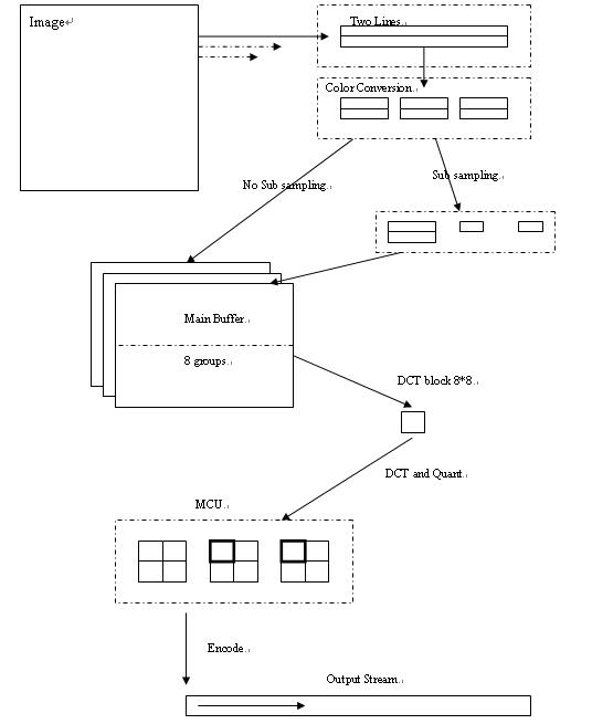
This article focuses on data structures which are used during whole JPEG compressing process. This will help to understand the data flow in JPEG.
Input Buffer
Input buffer is the image buffer for compressed. The line of image will be input into JPEG line by line.
Color Buffer
Color buffer includes two line and 3 components. Read each line from image and convert to YCC color space.
After read two lines from image, it can do sub sampling.
If no need to do sub sampling, just copy the data to main buffer, the two lines will be seen as a group.
If need do sub sampling, do sub sampling for Cb and Cr components, then copy them to Main buffer.
Main Buffer
Main buffer include 3 components. It defines different size for 3 components. It depends on sub sampling or not.
Main Buffer includes 16 lines pixels of input image. At vertical direction, it is two block width. At horizontal direction, it will include (width+7)>>3 block width. If the right edge doesn’t meet the requirement, it will be expanded.

DCT workspace
DCT workspace is 8*8 size block. DCT is done at this local area and quant is too.
The blocks are gotten from Main buffer by MCU.
MCU
MCU is standard 16*16 pixels in original image. Because of sub sampling, Cb, Cr components may just include 1 block. So for sub sampling case, MCU include 6 blocks. For no sub sampling case, MCU include 12 blocks.
Output Stream
Whole MCU will be encoded together, after encoded; the bits will be output to a stream.
In JPEG, the output stream is default 64KB, if the size will greater than it, reallocate it, the increment is 64KB
For Decompress process
Now that the compression buffers have been known, then for decompressing, it is same. And data flow is inverse direction.