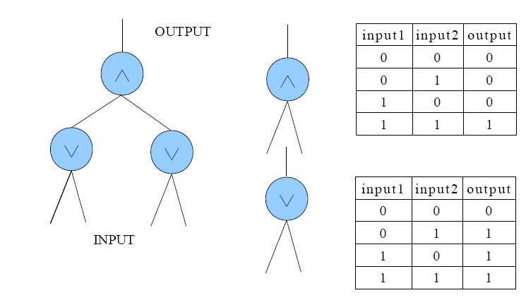
In the Design of Digital Logic class, Sheryl is asked to design a device which can produce a digital signal (a sequence of 0 and 1), given by the professor. After several sleepless nights, she completes a kind of Boolean circuit which looks like a complete binary tree as showed in Figure 1. Every node of the tree is a Boolean arithmetic unit (BAU) which takes in inputs from its both children and produce an output to its parent. The inputs of BAU are either 1 or 0, and the output should be calculated due to the type of BAU which is either ∧ or ∨. The truth tables of the two types are also showed in Figure 1. The INPUT of Sheryl's circuit is the sequence of inputs of the lowest-level BAUs and the OUTPUT is the output of the top BAU.

Figure 1
To accomplish the assignment, Sheryl has to manually handle the INPUT to produce the expected signal. For example, assuming Sheryl's circuit is the one showed in Figure 1, when the professor wants (0, 0, 0, 1, 1, 1) as the signal, the INPUT may alter as this: (0, 0, 0, 0) -> (0, 0, 1, 1) -> (1, 1, 0, 0) -> (1, 1, 1, 1) -> (1, 0, 1, 0) -> (0, 1, 0, 1). But this is too complex because Sheryl has to change the INPUT 14(2 + 4 + 2 + 2 + 4) times totally! So a more clever way is preferable, say (0, 0, 0, 0) -> (0, 0, 0, 0) -> (0, 0, 0, 0) -> (0, 1, 0, 1) -> (0, 1, 0, 1) -> (0, 1, 0, 1), which requires only 2(0 + 0 + 2 + 0 +0) changes of the INPUT.
Given Sheryl's circuit and the signal expected, your task is to find the minimal changes of the INPUT to produce the signal. Note the INPUT begins with all 0s.